The Moody Diagram
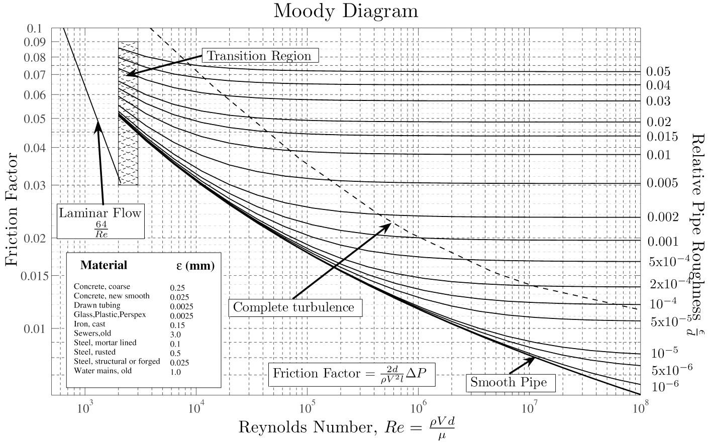
An Important Chart in Fluid Mechanics and LEV Design
LEVCentral Expert Commentary
If Fletcher’s Nomogram was the traditional graphical calculator for duct pressure losses, then the Moody Diagram is the chart that makes those calculations possible.
The Moody Diagram is one of the best-known engineering charts in fluid mechanics. Developed by Lewis Ferry Moody in 1944, it provides a graphical method of determining the Darcy friction factor for fluid flow in pipes and ducts. The friction factor is then used within the Darcy-Weisbach equation to calculate pressure losses due to friction.
Although originally developed for general fluid mechanics, the Moody Diagram has become an essential tool in ventilation engineering. It allows LEV designers to estimate the friction losses that occur as air travels through ductwork, enabling accurate fan selection and pressure loss calculations.
Today, engineers rarely use printed Moody charts in day-to-day work because the calculations are performed automatically within software, spreadsheets and mobile apps. Nevertheless, understanding how the Moody Diagram works remains one of the best ways of appreciating the engineering principles that underpin modern LEV design.
Moody Diagram
What is the Moody Diagram?
The Moody Diagram is a graphical representation of the relationship between:
- Reynolds Number (Re)
- Relative Pipe Roughness (ε/D)
- Darcy Friction Factor (f)
Once the friction factor has been obtained from the chart, it can be substituted into the Darcy-Weisbach equation to calculate friction pressure losses within pipes or ventilation ductwork.
Key Learning Points
The Moody Diagram helps engineers determine:
- Darcy friction factor.
- Pressure losses in ductwork.
- Pressure losses in pipework.
- The influence of duct roughness.
- The effect of Reynolds Number.
- Laminar flow behaviour.
- Transitional flow.
- Turbulent flow.
- Fully rough turbulent flow.
- Relative roughness effects.
- The relationship between friction factor and pressure loss.
- Fan pressure requirements.
Understanding the Three Flow Regimes
One of the strengths of the Moody Diagram is that it illustrates how friction behaves differently depending upon the nature of the airflow.
| Flow Regime | Reynolds Number | Characteristics |
|---|---|---|
| Laminar Flow | Below approximately 2,300 | Smooth flow with little mixing. Friction depends almost entirely on Reynolds Number. |
| Transition Zone | Approximately 2,300–4,000 | Unstable flow where behaviour becomes unpredictable. Pressure loss calculations are less reliable. |
| Turbulent Flow | Above approximately 4,000 | The regime encountered in almost all industrial LEV duct systems. Friction depends upon both Reynolds Number and duct roughness. |
Industrial LEV systems are almost always designed to operate within the turbulent flow region, where transport velocities are sufficient to keep contaminants suspended within the ductwork.
Why is it Important in LEV?
Every duct system creates resistance to airflow.
As air passes through straight ductwork, friction develops between the moving air and the duct wall. The greater the friction, the greater the pressure loss and the harder the fan must work.
The Moody Diagram enables engineers to estimate this resistance by taking account of:
- duct diameter;
- air velocity;
- airflow regime;
- internal surface roughness; and
- fluid properties through the Reynolds Number.
These friction losses form a major component of the system resistance used during LEV design and fan selection.
Source Information
Developer: Lewis Ferry Moody
First Published: 1944
Resource Type: Engineering Design Chart
Primary Topics: Darcy Friction Factor, Darcy-Weisbach Equation, Pressure Loss, Duct Design, Fluid Mechanics, LEV Design, Fan Selection.
LEVCentral Perspective
The Moody Diagram is one of those engineering tools that every LEV designer should understand—even if they never actually use the printed chart.
Modern software performs these calculations instantly, but unless engineers understand what the program is calculating, it becomes difficult to recognise when results appear unreasonable.
The Moody Diagram also demonstrates an important engineering principle:
Pressure loss is influenced by much more than airflow alone.
Internal duct roughness, duct diameter and airflow regime all affect friction losses. Two ducts carrying exactly the same airflow may therefore require significantly different fan pressures simply because one is rougher or smaller than the other.
Understanding these relationships leads to better fan selection, lower energy consumption and more efficient LEV systems.
Further Resources
- Fletcher’s Nomogram – Traditional graphical method for estimating duct friction losses.
- OXYL8 LEV App – Includes a growing range of practical LEV engineering calculators, replacing many of the traditional nomograms and charts used by earlier generations of engineers.
- Basic LEV Maths – Fan Laws (OXYL8 / LEVCentral)
- ACGIH – Industrial Ventilation: A Manual of Recommended Practice for Design
- HSG258 – Controlling Airborne Contaminants at Work
Recommended Learning
- M505 Control of Hazardous Substances
- P600 Methods for Testing Performance of LEV
- P601 LEV Thorough Examination & Testing
- P602 LEV Basic Design Principles
- P604 LEV Commissioning & Performance Evaluation
Thought Leadership
Before computers, engineers relied on engineering charts such as the Moody Diagram and Fletcher’s Nomogram because solving the governing equations by hand was both time-consuming and impractical. Those graphical methods allowed complex calculations to be performed quickly using nothing more than a ruler and a good understanding of fluid mechanics.
Today, software performs those same calculations almost instantly, yet every spreadsheet, duct calculator and smartphone app is still based on the same relationships between Reynolds Number, surface roughness, friction factor and pressure loss first brought together in Moody’s chart.
From a LEVCentral perspective, understanding the Moody Diagram is less about learning to read a chart and more about understanding how ventilation systems really behave. Engineers who understand the underlying physics are far better equipped to diagnose poorly performing systems, optimise duct designs and select fans that deliver both effective contaminant control and energy-efficient operation. That knowledge remains just as valuable today as it was when Lewis Moody first published his famous diagram over eighty years ago.
Useful diagram for estimating the relative duct roughness factor in calculating pressure losses in ducts.
Additional Notes
Reynolds Number (Re) a dimensionless number which is obtained from
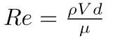 where
where  is the density of the air at temp and pressures prevailing and
  is the Viscosity of the air. V is the velocity in the duct, d is the diameter of the duct.
Almost all LEV systems run with the Re above 2000 ie in the turbulent zone.


You must be logged in to post a comment.